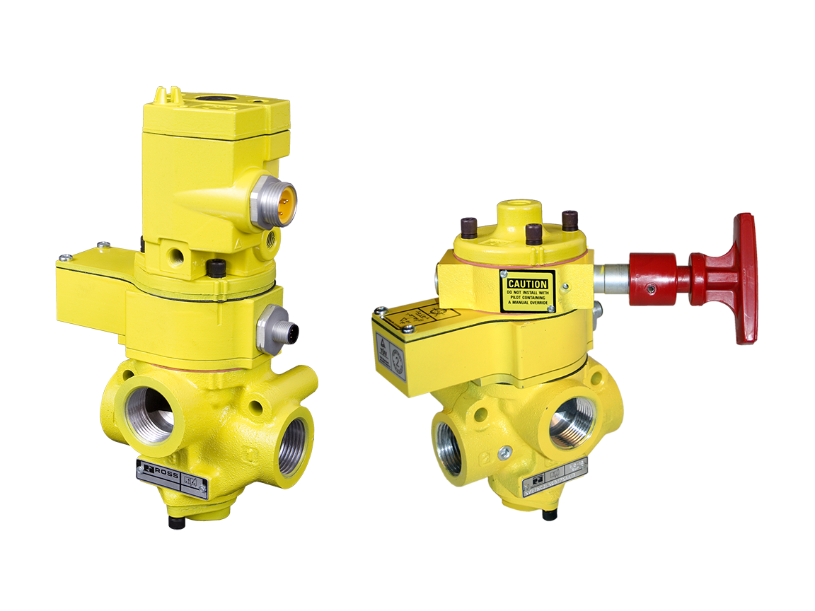
SV27 Series Single Valve Safety Category. 2 PL c, External Monitoring with & without Manual Lockout L-O-X®
- Poppet construction for near zero leakage
- Dirt tolerant, wear compensating poppet design for quick response and high flow capacity
- Senses internal position & state
- Electrical feedback via DPST switch (Double-Pole Single-Throw)
- Directly operated safety-rated force-guided positive-break status switch (DPST)
- A diagnostic coverage (DC) of 99% can be obtained by monitoring the safety switch status
- Includes integrated 1/8" sensor port for pressure verification with either a visual pop-up indicator or electrical pressure switch
- L-O-X® design only allows the valve to be lockable in the OFF position
- SISTEMA Library available for download
loading...
loading...
Product Overview
The ROSS Controls SV27 Series Sensing Valves combine the proven durability and high-flow performance of ROSS's 27 Series poppet valve platform with integrated position and state monitoring, creating a single-valve safe exhaust solution with 99 percent diagnostic coverage. When monitored by an external safety control system, the SV27 achieves Safety Category 2, Performance Level c (PL c) per ISO 13849-1:2015, with TUV Rheinland certification to SIL 2 per IEC 61508 and IEC 61511.
Electrical feedback is provided through a positively-driven, safety-rated DPST (Double-Pole Single-Throw) force-guided switch that is directly actuated by actual poppet position and state, not inferred from pressure or electrical signals alone. The DPST switch provides both normally open (NO) and normally closed (NC) contacts, enabling direct dual-channel monitoring by safety PLCs and safety relays. For 3/4 inch and 1-1/4 inch body sizes, the switch is actuated whenever the valve is NOT in its normal home position. For 2 inch body sizes, the switch is actuated only when the valve IS in the normal home position.
The SV27 platform offers an optional integrated 1/8 inch NPT pressure verification port (PV) for independent confirmation of downstream pressure state. This port accepts either a visual pop-up pressure indicator (model 988A30) for operator confirmation or an electrical pressure switch (model 586A86, factory preset at 5 psi falling edge) for electronic feedback to the safety controller. These accessories enhance the overall safety architecture by providing a separate, independent verification channel.
The optional L-O-X lockout design variant allows the valve to be padlocked in the OFF (exhausted) position, enabling full lockout/tagout compliance per OSHA 29 CFR 1910.147 and ANSI Z244.1 without requiring a separate upstream lockout device. The L-O-X design physically prevents the valve from being energized while locked, providing positive energy isolation at the zone valve level.
SV27 valves are available in 3/4 inch through 2-1/2 inch body sizes with 9 port size configurations, covering flow capacities from 6.2 Cv (6,100 Nl/min) through 66 Cv (65,000 Nl/min). Both solenoid pilot controlled and pressure (pneumatic pilot) controlled actuation options are offered. The B10D reliability rating exceeds 20,000,000 cycles, and the MTTFD is 98.15 years, confirming suitability for high-cycle safety applications. SISTEMA Library files are available for download.
Key Engineering Features
- Integrated DPST Safety Switch (99% Diagnostic Coverage) - Positively-driven, force-guided Double-Pole Single-Throw switch with both NO and NC contacts. Directly actuated by poppet position. Monitoring both contacts on each cycle achieves 99% diagnostic coverage per ISO 13849-1, enabling Category 2 compliance with a single valve.
- TUV Rheinland Certified SIL 2 / PL c - Third-party certified to SIL 2 per IEC 61508 and IEC 61511, and PL c per ISO 13849-1:2015. In redundant configurations, achieves CAT 3, PL e.
- 27 Series Poppet Construction - Built on ROSS's proven 27 Series poppet platform: near-zero internal leakage, dirt-tolerant, wear-compensating, quick response, and high flow capacity without requiring in-line lubrication.
- Pressure Verification Port (PV) - Optional 1/8" NPT integrated port for downstream pressure verification using a visual pop-up indicator (988A30) or an electrical pressure switch (586A86, preset 5 psi falling edge), providing independent confirmation of pressure release.
- Optional L-O-X Lockout Design - Variants include integrated L-O-X lockout capability allowing the valve to be padlocked in the OFF position, enabling zone-level pneumatic lockout/tagout compliance without a separate upstream lockout valve.
- Wide Body Size Range (3/4" to 2-1/2") - Nine body configurations cover flow from 6.2 Cv to 66 Cv (6,100 to 65,000 Nl/min), accommodating applications from compact single-actuator circuits to large-bore cylinder and high-flow zone protection.
- Solenoid and Pressure Pilot Actuation - Available in solenoid pilot controlled (24 VDC, 110-120 VAC, 230-240 VAC) and pressure (pneumatic pilot) controlled versions, providing actuation flexibility for diverse control system architectures.
- Rated for 15 Million-Plus Cycles - Switching frequency rated in excess of 15 million cycles with a B10D of 20,000,000 cycles and MTTFD of 98.15 years, demonstrating exceptional reliability for continuous duty safety applications.
- Non-Locking Manual Override - Flush rubber non-locking manual override standard on solenoid models for commissioning and maintenance, with optional locking and extended override variants available.
- SISTEMA Library Available - Downloadable SISTEMA Library files containing all safety parameters for ISO 13849-1 safety function verification and documentation.
Technical Specifications
General Specifications
| Parameter | Specification |
| Safety Category | Category 2 (single valve); CAT 3, PL e possible in redundant configuration |
| Performance Level | PL c per ISO 13849-1:2015 |
| Safety Integrity Level | SIL 2 per IEC 61508 and IEC 61511 (TUV Rheinland certified) |
| Diagnostic Coverage | 99% (monitoring DPST switch NO and NC contacts on each cycle) |
| MTTFD | 98.15 years (nop: 7,360 cycles/year) |
| PFHD | 2.35 x 10^-7 per hour |
| B10D Rating | 20,000,000 cycles |
| Valve Function | 3/2 normally closed (safe exhaust / dump) |
| Construction | Poppet (27 Series platform) |
| Actuation | Solenoid pilot controlled (24 VDC; 110-120 VAC; 230-240 VAC) or pressure (pneumatic pilot) controlled |
| Switch Type | DPST (Double-Pole Single-Throw), positively-driven, force-guided, safety-rated |
| Switch Contact Rating (Max) | 2.5 A / 120 VAC |
| Switch Contact Rating (Min) | 50 mA / 24 VDC |
| Body Sizes | 3/4", 1", 1-1/4", 1-1/2", 2", 2-1/2" |
| Port Configurations (body designations) | 540, 550, 560, 760, 770, 780, 980, 990, 995 |
| Flow Capacity (3/4" body, 1/2" x 1") | 6.2 Cv (6,100 Nl/min) |
| Flow Capacity (3/4" body, 3/4" x 1") | 8.2 Cv (8,100 Nl/min) |
| Flow Capacity (1" body) | 9.1 Cv (9,000 Nl/min) |
| Flow Capacity (1-1/4" body, 1" x 1-1/2") | 21 Cv (21,000 Nl/min) |
| Flow Capacity (1-1/4" body, 1-1/2" x 1-1/2") | 29 Cv (29,000 Nl/min) |
| Flow Capacity (1-1/2" body) | 30 Cv (30,000 Nl/min) |
| Flow Capacity (2" body, up to 2-1/2") | 45-57 Cv (44,000-56,000 Nl/min) |
| Flow Capacity (2-1/2" body) | 66 Cv (65,000 Nl/min) |
| Operating Pressure | 40-150 psig (2.8-10.3 bar) |
| Ambient Temperature | 40-120 F (4-50 C) |
| Media Temperature | 40-175 F (4-80 C) |
| Flow Media | Filtered air; 5-micron minimum filtration required |
| Solenoid Power (24 VDC) | 14 watts per solenoid (continuous duty) |
| Solenoid Power (110-120 VAC, 50/60 Hz) | 87 VA inrush; 30 VA holding |
| Solenoid Enclosure | IP65 |
| Pressure Verification Port | Optional 1/8" NPT |
| Manual Override | Flush, rubber, non-locking (solenoid models standard) |
| Port Threads | NPT and G (BSPP) |
| Valve Body Material | Cast aluminum |
| Poppet Assembly Material | Acetal and stainless steel |
| Spool (Lockout) Material | Stainless steel |
| Seal Material | Buna-N and fluorocarbon options |
Flow Performance Data
| Body Designation | Body Size | Port Config (In x Out/Exh) | Cv (Nl/min) | Weight |
| 540 | 3/4" | 1/2" x 1" | 6.2 (6,100) | 4.5 lbs |
| 550 | 3/4" | 3/4" x 1" | 8.2 (8,100) | 4.5 lbs |
| 560 | 1" | 1" x 1" | 9.1 (9,000) | N/A |
| 760 | 1-1/4" | 1" x 1-1/2" | 21 (21,000) | 7.8 lbs |
| 770 | 1-1/4" | 1-1/2" x 1-1/2" | 29 (29,000) | 7.8 lbs |
| 780 | 1-1/2" | 1-1/2" x 1-1/2" | 30 (30,000) | N/A |
| 980 | 2" | 1-1/2" x 2-1/2" | 45-57 (44,000-56,000) | 18.1 lbs |
| 990 | 2" | 2-1/2" x 2-1/2" | 57 (56,000) | 18.1 lbs |
| 995 | 2-1/2" | 2-1/2" x 2-1/2" | 66 (65,000) | N/A |
Certifications & Compliance
| Certification/Standard | Detail |
| Safety Category / PL | Category 2, PL c per ISO 13849-1:2015 (single valve); CAT 3, PL e in redundant configuration. |
| Safety Integrity Level | SIL 2 per IEC 61508 and IEC 61511; TUV Rheinland third-party certified. |
| Diagnostic Coverage | 99% DC achieved by monitoring DPST safety switch NO and NC contacts on each actuation and de-actuation cycle. |
| MTTFD / PFHD | MTTFD: 98.15 years; PFHD: 2.35 x 10^-7 per hour. |
| B10D | 20,000,000 cycles. |
| CE Marking | CE marked per EU Machinery Directive 2006/42/EC and applicable EMC directives. |
| SISTEMA Library | Downloadable SISTEMA Library files available for ISO 13849-1 PL verification. |
Typical Applications & Industries
Metal Forming and Press Operations
- Mechanical power press clutch-brake control where the SV27 DPST switch provides safety controller confirmation of pneumatic clutch disengagement before permitting die access, satisfying OSHA 29 CFR 1910.217 press safety requirements.
- Metal stamping and blanking lines where 99% DC monitoring of the SV27 replaces a second valve in certain Category 2 architectures, reducing system cost and footprint.
- Tube and pipe bending machines where DPST switch feedback confirms poppet position during the safety stop before operator material loading.
- Hydraulic press pneumatic control circuits where air pilot pressure must be verified absent before hydraulic pump isolation maintenance.
Injection Molding and Plastics Processing
- Injection molding machine pneumatic core pull and ejector circuits where SV27 L-O-X variants enable the mold technician to lock out the zone valve during mold change, with DPST switch feedback confirming lockout state.
- Blow molding parison handling systems requiring confirmed pressure release at the preform gripper circuit before manual intervention.
- Thermoforming clamp and trim die actuators where monitored exhaust confirmation prevents mold area access until the SV27 DPST switch reports the safe state.
Automotive and Heavy Equipment Assembly
- Body assembly fixture clamping circuits where the SV27's high Cv options (up to 66 Cv) depressurize large-bore clamp cylinders rapidly, reducing safety stop-to-access time.
- Engine and transmission assembly test stand pneumatic controls requiring verified pressure removal before operator fixture interaction, with DPST signals feeding the machine safety PLC.
- Heavy equipment cab and frame assembly jigs with large pneumatic actuators where the 2 inch and 2-1/2 inch body SV27 provides the required flow and monitoring capability.
Food and Beverage and Pharmaceutical Processing
- Filling and capping machine pneumatic actuators where documented 99% DC monitoring satisfies validation requirements for FDA-regulated machinery in pharmaceutical and food safety audits.
- Sanitary wash-down environments where IP65-rated solenoid enclosures and stainless steel spool materials in L-O-X variants resist corrosion during CIP and washdown procedures.
- Packaging and form-fill-seal machine pneumatic circuits requiring rapid exhaust and position verification for quick access during format change.
Woodworking and Panel Processing
- Panel press and laminating machines where large-bore pneumatic clamp cylinders require high-Cv safe exhaust with DPST monitoring to confirm depressurization before panel unloading.
- CNC router vacuum fixtures and hold-down systems requiring verified vacuum release and pressure confirmation before part removal.
General OEM and Industrial Machinery
- OEM machine designs requiring Category 2 safe exhaust with documented 99% DC for CE marking and EU Machinery Directive technical file compliance.
- Multi-zone pneumatic systems where individual SV27 valves per zone provide zone-selective monitoring feedback, allowing zone-specific access without shutting down adjacent production zones.
- ATEX-classified areas where the pressure-controlled (no solenoid) SV27 variant eliminates ignition risk from electrical actuation in potentially explosive atmospheres.
Ordering and Model Number Configuration
SV27 model numbers encode the valve function, body designation, actuation type, and voltage. Example: SV27NC305407PSAA1A = SV27 Series, normally closed, 540 body (3/4" ports), solenoid pilot, 24 VDC. Contact ROSS Controls for the complete variant configurator.
|
SV27 Series Model Number Structure:
SV27 Series designation (Sensing Valve, 27 Series platform)
NC/DC Function (NC = Normally Closed; DC = specific configurations)
3054 Body designation (e.g., 540 = 3/4" body, 1/2" in / 1" out)
07 Actuation code (07 = solenoid pilot; P = pressure pilot)
PS Valve sub-type/option code
AA Additional option codes
1A Voltage / connection code (1A = 24 VDC) |
Available voltages: 24 VDC (continuous duty); 110-120 VAC 50/60 Hz; 230-240 VAC 50/60 Hz.
L-O-X lockout variant available: specify lockout option at time of ordering.
Pressure verification port (PV) option: 1/8" NPT. Specify visual indicator (988A30) or electrical pressure switch (586A86) as accessory.
NPT and G (BSPP) thread options available.
Manual override options: standard non-locking (standard), locking (792K87), extended (791K87), extended with palm (984H87).
Prewired cable kits for solenoid and DPST switch connectors available (2m, 4m, 10m).
SISTEMA Library files downloadable at rosscontrols.com.
Contact ROSS Controls at (800) 438-7677 for full configurator, dimensional drawings, and CAD models.
Accessories
Visual Pressure Indicator (Model 988A30)
Pop-up visual indicator for the 1/8" NPT pressure verification port. Confirms pilot or downstream pressure presence with a mechanical pin, providing operator-visible verification without electrical connection.
Electrical Pressure Switch (Model 586A86)
Factory preset at 5 psi falling edge. DIN EN 175301-803 Form A connector. Provides electrical feedback signal to safety controller confirming pressure release at the SV27 outlet circuit.
Solenoid Indicator Light Kits
LED indicator kits for solenoid energized-state visualization: Model 862K87-W (24 VDC), 862K87-Z (110-120 VAC, 50-60 Hz), 862K87-Y (230 VAC, 50-60 Hz).
Prewired Cable Kits (Solenoid)
Models 2239H77 (4m) and 2240H77 (10m): MINI 3-pin connector to flying leads for solenoid wiring.
Prewired Cable Kits (DPST Switch)
Models 2241H77 (4m) and 2242H77 (10m): M12 5-pin connector to flying leads for DPST safety switch wiring to safety controller.
Manual Override Options
Locking button (792K87), extended non-locking button (791K87), and extended palm-contact button (984H87) as alternatives to the standard flush non-locking override.
Related Products & Accessories
- MDC1 Series Single Valve (Category 1, PL c) - Entry-level safe exhaust single valve without monitoring for lower-risk applications. https://www.rosscontrols.com/en/series/1291-mdc1-series-single-valve
- MDC2 Series Single Valve (Category 2, PL c) - MDC platform with integrated solid-state pressure sensor for Category 2 with 60-90% DC. https://www.rosscontrols.com/en/series/1292-mdc2-series-single-valve
- DM1 Series C Double Valve (Category 4, PL e) - Redundant dual-poppet double valve with internal monitoring for the highest safety category. https://www.rosscontrols.com/en/series/1294-dm1-series-c-double-valve
- M35 Series Double Valve (Category 4, PL e, External Monitoring) - Redundant dual-poppet double valve with external solid-state pressure sensor monitoring. https://www.rosscontrols.com/en/series/1296-m35-series-double-valve
- Lockout L-O-X Valves (15 Series) - Stand-alone manual lockout valves for upstream pneumatic energy isolation. https://www.rosscontrols.com/en/series/1287-lockout-valves-15-series
Frequently Asked Questions (FAQ)
Q: What safety category and PL does the SV27 achieve?
A: The SV27 Series achieves Safety Category 2, Performance Level c (PL c) per ISO 13849-1:2015 as a single valve when the DPST switch is monitored on each actuation and de-actuation cycle. In a redundant (1oo2) configuration with two SV27 valves, the architecture can achieve Category 3, PL e. The valve is TUV Rheinland certified to SIL 2 per IEC 61508 and IEC 61511.
Q: How does the DPST switch provide 99% diagnostic coverage?
A: The DPST switch is positively driven directly by the poppet mechanism and has both normally open (NC) and normally closed (NO) contacts. By monitoring both contacts simultaneously on every valve cycle, the safety controller detects virtually all faults that would prevent the valve from transitioning between states, including poppet sticking, switch contact welding, and wiring faults. This two-channel monitoring on a force-guided switch achieves 99 percent DC per ISO 13849-1.
Q: How does the DPST switch behave differently on 3/4"/1-1/4" versus 2" body valves?
A: For 3/4 inch and 1-1/4 inch body sizes, the DPST switch is actuated whenever the poppet is NOT in the normal home (de-energized/exhausted) position. Any movement from home triggers the switch. For 2 inch body size, the DPST switch is actuated only when the poppet IS in the normal home position. This design difference must be accounted for in the safety controller monitoring logic and in SISTEMA calculations.
Q: What is the SV27 pressure verification port (PV) and how is it used?
A: The optional 1/8 inch NPT pressure verification port is a sensing tap on the downstream side of the valve. Installing a visual pop-up indicator (model 988A30) gives operators a mechanical confirmation that outlet pressure has been released before accessing the machine. Installing an electrical pressure switch (model 586A86, preset at 5 psi falling edge) provides electronic confirmation to the safety controller, adding an independent verification channel to the safety architecture.
Q: Can the SV27 be locked out for maintenance?
A: Yes, the L-O-X lockout variant allows a padlock to be applied to the valve in the OFF (exhausted) position, physically preventing solenoid energization. This enables zone-level pneumatic lockout/tagout at the SV27 valve itself, satisfying OSHA 29 CFR 1910.147 energy control procedures for the protected circuit without requiring a separate upstream lockout device.
Q: What body sizes and flow capacities are available?
A: The SV27 is available in 9 body configurations from the 3/4 inch body through the 2-1/2 inch body. Flow capacities range from 6.2 Cv (6,100 Nl/min) for the 3/4 inch body with 1/2 inch ports, to 66 Cv (65,000 Nl/min) for the 2-1/2 inch body. This range accommodates everything from compact single-cylinder circuits to large-bore, high-flow zone isolation applications.
Q: What actuation options are available?
A: The SV27 is available in solenoid pilot controlled (24 VDC, 110-120 VAC 50/60 Hz, and 230-240 VAC 50/60 Hz) and pressure (pneumatic pilot) controlled versions. The pressure-controlled option eliminates the solenoid entirely, which is useful for ATEX-classified areas or where electrical actuation is not practical.
Q: What are the B10D and MTTFD values?
A: The SV27 has a B10D of 20,000,000 cycles and an MTTFD of 98.15 years (based on nop of 7,360 cycles per year). The PFHD is 2.35 x 10^-7 per hour. These values are used in ISO 13849-1 calculations to verify the achievable Performance Level for a given application's cycle rate and mission time.
Q: What filtration is required?
A: A minimum 5-micron upstream filter is required. Air quality should meet ISO 8573-1 Class 7:4:4. The operating pressure range is 40 to 150 psig (2.8 to 10.3 bar).
Q: What solenoid connection types are available?
A: Solenoid connection uses a MINI 3-pin connector with color-coded pinout (Green/Yellow = Ground, Blue, Brown). An M12 5-pin connector is also available for harsh environments. The DPST switch connection uses a MINI 3-pin connector for 3/4 inch and 1-1/4 inch body sizes and an M12 5-pin connector for 2 inch body sizes.
Q: Are prewired cable kits available?
A: Yes. Solenoid cable kits (models 2239H77 at 4m and 2240H77 at 10m) and sensing switch cable kits (models 2241H77 at 4m and 2242H77 at 10m) are available as accessories, with MINI 3-pin or M12 5-pin connectors to flying leads.
Q: Is a SISTEMA Library file available?
A: Yes. A SISTEMA Library file containing the SV27 safety parameters is available for download from rosscontrols.com, enabling ISO 13849-1 PL verification without manual data entry.
Q: What warranty and support does ROSS provide?
A: ROSS Controls provides a one-year warranty on all products. Technical support is available at 1-888-TEK-ROSS. Customer service: 1-800-GET-ROSS. Global support through ROSS offices in the USA, Canada, Germany, France, UK, Brazil, India, China, and Japan.
Installation & Maintenance Guidelines
- Install the SV27 in the supply line with all protected actuators and devices downstream of the valve exhaust port.
- Verify operating pressure is within 40 to 150 psig (2.8 to 10.3 bar). Supply air must be filtered to 5-micron minimum.
- Wire both DPST switch contacts (NO and NC) to the safety controller's dual-channel input. Do not use only one contact, as both channels are required for 99% diagnostic coverage.
- If using the pressure verification port, install either the visual indicator or electrical pressure switch and verify the installation does not restrict the sensing port.
- For L-O-X lockout variants, verify the lockout mechanism engages fully and prevents solenoid energization when locked. Train personnel on the lockout procedure.
- Perform commissioning functional test: energize solenoid, verify supply to downstream, confirm DPST switch state transition; de-energize, verify exhaust, confirm DPST returns to home state.
- For solenoid models, verify solenoid LED indicator (if installed) correctly indicates energized/de-energized state.
- Program the safety controller to monitor DPST switch transitions on every cycle and generate a safety stop on missing or incorrect state transitions.
- Establish periodic proof test intervals based on nop and machine mission time per ISO 13849-1 Annex C.
- Document all installation, commissioning, and periodic test records for the machine technical file.
Warranty & Global Support
ROSS Controls provides a one-year warranty on all products, covering defects in material and workmanship from date of purchase.
Technical support: 1-888-TEK-ROSS (1-888-835-7677). Customer service: 1-800-GET-ROSS (1-800-438-7677).
Global support through ROSS offices in the USA (Ferndale, Michigan), Canada, Germany, France, United Kingdom, Brazil, India, China, and Japan.
SISTEMA Library files, dimensional drawings, CAD models, and certifications available at rosscontrols.com.
Download Catalog: https://www.rosscontrols.com/en/documents/381
Download Documents
SV27 Series Single Valve
